Building an Autonomous Mars Rover with JAXA
- 23 minsSummary
This article summarizes the experiences of building a highly-reliable system by imitating a Mars rover during my master’s course at NAIST in 2015. Although the rover was built with “toy” parts, the complexity and thought that went into its design, management, and implementation are very significant.
This project is a great example of how even after careful design and implementation, there are unexpected things that might go wrong when you least expect it. This is why all critical systems are required to satisfy a one-fail safe constraint, which we didn’t.
Introduction
Space has always been and still is, a mystery. We have certainly reached many milestones in interplanetary exploration, from the International Space Station (ISS) to the recent landings of the Falcon by SpaceX. Every single undertaking is very costly and many lives are at risk, so ensuring high reliability is key to safely pushing the boundaries. From design to building and operation, software is the driving power to ensure safety, reliability, and control.
Building software systems when the stakes are extremely high, in a highly uncertain environment with many physical constraints, has always been a challenge. In such environments, there is no room for mistakes. From the failure to convert from English units to metric ones in the NASA’s Mars Climate Orbiter in 1998 (with a cost of 125 million dollars), to the infamous self-destructing Ariane 5 Flight 501 because of incorrect integer size (with a cost of 8.5 billion dollars), we have seen that even the smallest mistakes can be fatal.
During my master’s course at Nara Institute of Science and Technology (NAIST), and in cooperation with the Japan Aerospace Exploration Agency (JAXA), I had the opportunity to participate in a project through which we had the opportunity to learn how highly-reliable systems are built. The course was done while working closely with professors from NAIST and engineers from JAXA. This article is a short description of the experiences and the lessons learned from the course. The course was conducted in Japanese, so some of the references and diagrams might be in Japanese if no English counterpart exists.
IT Triadic
Nara Institute of Science and Technology (NAIST) is a public graduate school located at the border of Nara, Osaka, and Kyoto. IT Triadic is an extra-curricular program held annually at NAIST with the goal to create “multi-specialists” across software, robotics, and information network security. The program has four tracks: Keys, RT, Spiral and Triadic, each with an increased focus in one of the three fields mentioned before. Further on, the Triadic track will be described, which has equal focus on the three fields.
The Triadic track has the goal to nurture skills required to lead the system development in one of the specialized fields. It aims at building the skills necessary to view a product from the user, manager, and product planning standpoints, while developing the technical skills for its execution. The Mars Rover course was one of the required courses to successfully finish the IT Triadic program, which is the topic of this article.
The Course
The Goal
As the course name suggests, the idea was to build a Mars rover using Lego Mindstorm EV3. Using the “toy” Mars rover, the challenge was to finish two missions: autonomous navigation and habitability investigation. The main aim of this course was obviously not to build something we will send to Mars, but to learn the difficulties in developing a highly reliable embedded system through a hands-on experience.
The two missions are outlined in the image below. The first mission is about traversing a line and avoiding obstacles. Once the edge of the crater is reached, the mission can be concluded successfully. The second mission is about discovering materials (colored stickers on the ground) while avoiding obstacles. Each mission is described in more details later on.
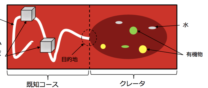
The course lasted for 4 months, in parallel with other courses as part of the Master’s program and/or the IT Triadic program. This, as well as the ongoing research we had in our labs, dictated the time we could dedicate to this course, which proved to be very limited.
Within that period, there were required documents that had to be submitted to the customer (JAXA) such as:
- Project plan, including roles, timeline, tooling, and so on.
- Operation scenario analysis for the missions.
- Software requirement analysis for the missions (functional and non-functional)
- Software traceability matrix between the mission and software requirements
- Test specifications based on the software requirements
- Test traceability matrix between the software requirements and test specifications
- Reports on the results of the above steps
Of course, during the same period, we had to design the rover and build the necessary software. We also had intermediate and final presentations during which we reported our results in front of all students and JAXA engineers.
The Role of JAXA
As mentioned earlier, the course was done in cooperation with the Japan Aerospace Exploration Agency (JAXA). During the course, JAXA represented the customer. They were available to answer any questions regarding the system, and clear out any ambiguities (some purposefully introduced) in the requirements. All of the questions were asked through a Q&A site so that every team has access to the asked questions and no duplicates arise.
The Team
Around 30 students from various laboratories participated in the project, divided into teams of either 3 or 4 members. Each team had to assign a project/product manager, who had the responsibility to organize the team, balance the workload per team member, prepare the necessary tooling, communicate with the customer, prepare the necessary documents, and lead the system development. Each team was randomly assembled.
I was teamed with Kanehira-san, Katou-san, and Norikane-san, and after discussing for a while we decided that I will be the one to take the role as the project manager of our team. This represented a huge challenge, as my Japanese at the time was somewhat limited, and my teammates’ English was even more so. Internal communication wasn’t much of an issue, but the preparation of the documents was. Since I wanted all the planning to be done together as a team, we decided to write the required documents in parallel with our discussions and planning. This made us craft high-quality, up-to-date documentation that anyone could use as a reference as to what exactly was decided at each step of the process.
Mission 1
Mission one was all about autonomously following a line and avoiding obstacles presented at random locations. Neither the shape nor the position of the obstacles was previously known.
In case the rover detected an emergent condition (such as not being able to find the line or avoid the obstacle successfully) and reported it to the ground station, the ground station was allowed to send pre-defined commands to bring the rover back on track. As the command byte size was limited, more complex commands were required rather than simply creating something like a remote-controlled toy car.
In order to successfully finish the mission, the rover had to avoid all obstacles successfully, stay within 60cm of the line, and stop just in front of the crater without entering, all under 15 minutes.
Mission 2
Mission 2 was the more challenging bit. Aside from obstacle avoidance, the rover was to autonomously roam around a crater and detect substances (colored stickers on the ground). The detected substance was then to be reported to the ground station, and the same process was repeated until all substances were detected.
The same rules about sending commands only when the rover reports an emergent situation applied, but it was taken a step further. While in the crater, we were sent a picture of the condition of the rover every minute, and that was the only visual information we had on the rover. That meant even if the rover reported an emergent situation, we had to wait at most 1 minute before knowing what kind of command to send to it. Moreover, we were only allowed to send a single command in a period of 1 minute, which slowed things down even more in case of an emergent situation.
To successfully finish the mission, the rover was supposed to detect 3 different substances and exit from the crater, without hitting an obstacle. The same 15 minutes limit also applied to this mission.
The Implementation Process
Autonomous control, which is absolutely difficult, is essential in the operation of the on-orbit space system. The on-orbit system is not always visible and the communication with the ground systems are not always available. These limitations were simulated in our project and made us very carefully think about how we can build a robust autonomous navigation while being able to efficiently handle emergency situations when they arise.
There were many other challenges that we had to deal with. For example, we were only allowed to use the test environment once for 30 minutes on a fixed date, regardless of the completeness of our system. We didn’t know the friction of the surface, which makes it really difficult to make certain length movements and turns. The sensors lacked accuracy. The hardware we could use was limited. Some of these were not obvious at all without a careful investigation.
Looking at the requirements for the course, you might notice how waterfall-like the process is. Although for certain aspects we were encouraged to use more agile processes, there were tasks that had to be done ahead of time while there are still many uncertainties remaining. I encouraged doing a lot of pair-programming in our team, which helped us move faster and develop a more reliable software, but that helped only with a small part of the myriad of potential problems we had to prepare for, mostly having to do with the uncertainty of the environment. The last couple of days we did marathons where we would code and test on our improvised environment together for many hours until we reached a state that was satisfactory for all of us.
Communication was also a challenge. All of us were busy with research and other courses. Timeslots when everyone is available were scarce. We had to be very careful with splitting responsibilities and synchronizing our progress. Language, on top of everything, also brought additional complexity to the project.
These are some of the many challenges that might not be obvious at first sight but pose a risk when building a system of this kind. Our approach is described in the following text.
Hardware
As one might imagine, the design of the rover plays a crucial role in how the software will be written, and ultimately how the system will be built. At our disposal, we had a Lego Mindstorm EV3 with all the parts shown in the diagram below. The only limitation was we were only allowed to choose up to 5 parts. It was possible to trade a part of the required parts with the ones marked not necessary if the design demanded it.
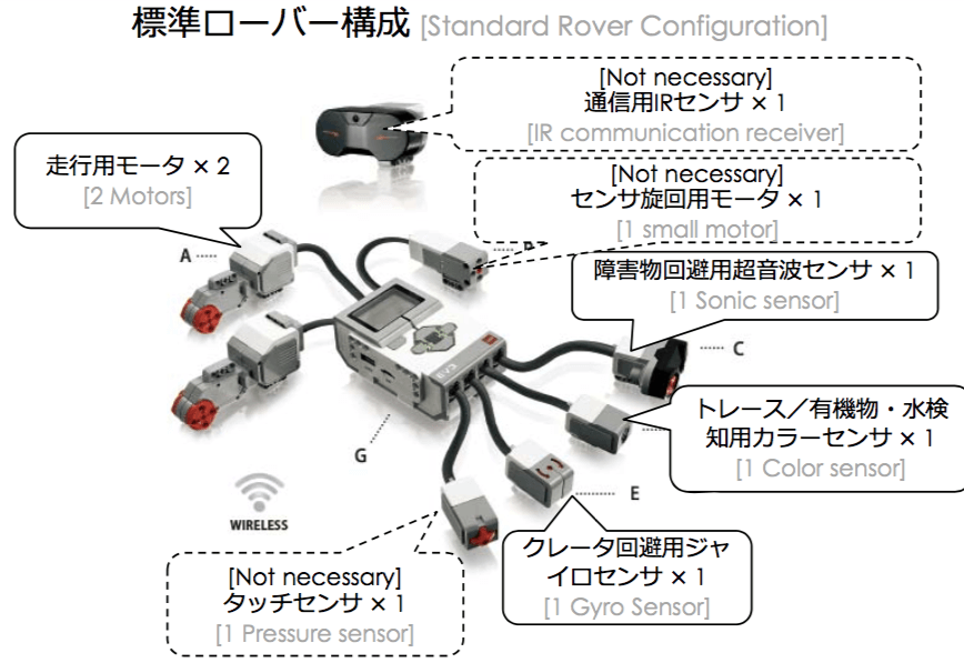
After some discussion, we decided to go with the standard set of parts, plus an additional color sensor that was approved by the customer. The color sensor was used for both tracing the white line and detecting the substances in the crater. The gyro sensor was used to detect when we are entering and exiting the crater (Y-axis). The sonic sensor was used to detect obstacles. We then went and did some sketches about the design, and we ended up with something as shown in the sketch below.
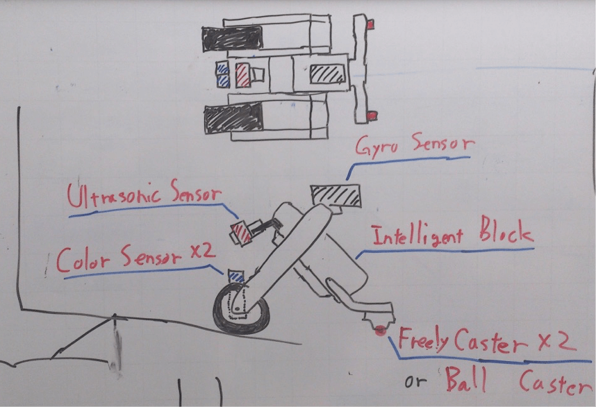
The reason we made the rover into an inverted-V shape is to handle edges better (entering and exiting the crater). If we were to make it flat like a car, it would have hanged at the edge of the crater when entering, ultimately ending our mission (something that happened to some of the other teams). Both engines were placed in the front, and a ball caster was placed in the back. As the engines were independently controlled, turns were done by putting power only through one engine, and the ball caster could easily follow.
The color sensor was positioned between the two driving motors because it had to be in the front for the line tracing, and it had to be close enough to the ground to be able to detect colors. The sonic sensor is able to measure distance somewhat accurately. We first tried positioning it at an angle so we can use it for detecting both obstacles and crater edges while inside the crater. As the distance between the ground and its position are fixed on a flat surface, changes in distance would signify either an obstacle or a crater edge, depending on the rate of change and speed of movement. Unfortunately, this approach wasn’t accurate enough, so we only used it for the detection of obstacles, and used the gyro sensor in order to detect edges. The gyro sensor was positioned so that we can measure changes in the Y-axis. This was to be used to detect whether we have crossed an edge or not and whether we have started ascending an edge before all the substances were detected.
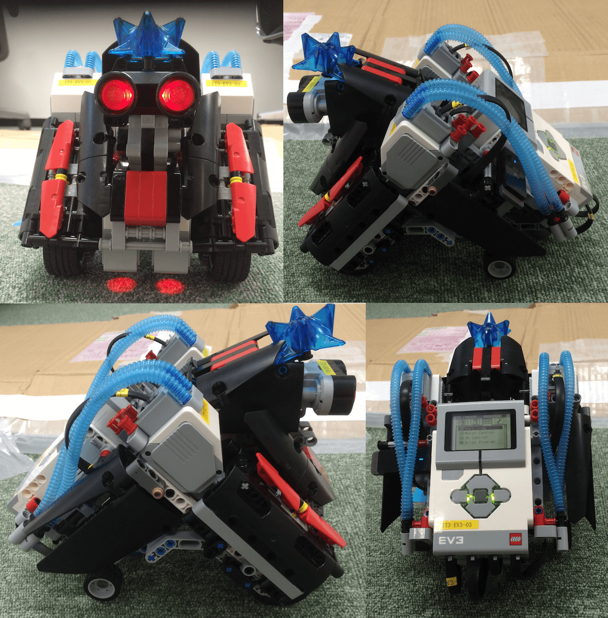
After putting the blocks together, we ended up with a rover as shown on the picture below. The blue pipes and star-like shape are purely decorative (it looks badass, right?).
Software
The Ground Station
The ground station is the software that is used by the engineers on Earth in order to communicate with the rover. The purpose of the ground station is to send commands to the rover, as well as receive messages about emergent situations and detected substances.
Although there was a ground station software provided by the lecturers, it was ambiguous to use, command-line based (read prone to errors), and closed-source, so we couldn’t do the adjustments we wanted to in order to achieve our goals. Because of that, we decided it is worth the effort to build our own ground station from scratch, ending up with what is shown in the screenshot below.
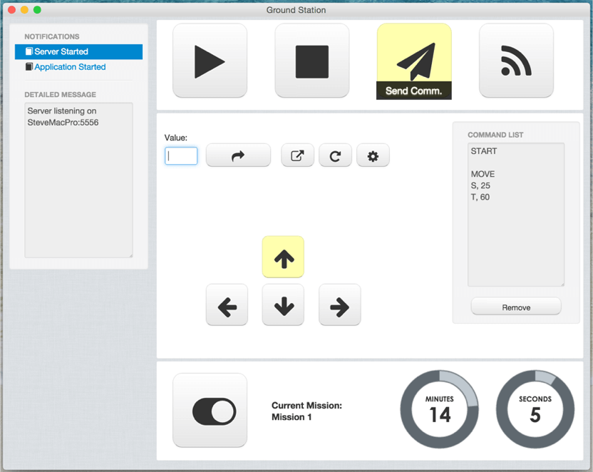
On the left-hand side, all notifications, whether from the ground station or the rover, are shown. This is where messages received by the rover are shown, and we can respond accordingly depending on the message. The top four buttons are used to start the rover (start a mission), stop the rover from moving, send the commands listed in the command list, and establish a connection with the rover.
The four arrow buttons represent the direction we want the rover to move in, the distance is written in the value field, and the curved arrow button will add that command to the command list. There are also buttons to clear the command list, and a button to enter into calibration mode (explained later on).
A simple timer with a toggle for the mission is also shown. Depending on the state of the toggle, different behavior is triggered in the Mars rover software. The timer starts when the start button is pressed, representing the remaining time for that mission.
Each button has a mouse-over message that describes what it does. Each button can also be controlled using the keyboard (such as the arrow keys). A log is kept for every command executed in the notifications section.
As mentioned earlier, the goal was to send and receive the shortest message possible while containing the most amount of information. As you can see in the picture, each command is represented by a single letter, along with its value. An empty row represents a different set of commands (for example, start, then move a certain distance, then stop). The message could be compressed and minimized even further, but this protocol was accepted by the customer, so we didn’t do any further optimizations.
The ground station was a cross-platform desktop application written in JavaScript using NW.js. The UI is just HTML and CSS.
The Mars Rover
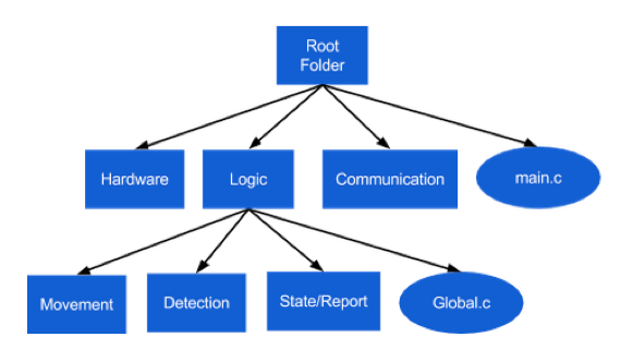
The rover code was written in C. Each of the software modules is shown in the diagram below. All modules are pretty self-explanatory, so there is no need for further description.
The rover and the ground station communicated through WebSockets, where the rover represented the server. They were connected to the same router with fixed IP addresses.
Calibrations
One thing that might not be obvious at first is the difficulty to travel a certain distance and turn at a certain angle without using an accelerometer and gyro sensor. The same amount of power sent to the engines will make the rover travel a very different distance depending on the friction of the surface. As speed is an important part of most movements done by the rover (such as turning and avoiding an obstacle), it was important to introduce a calibration step.
Although not mentioned before, we had 1 minute before the start of the missions to do whatever we like on the real terrain. We decided to use this time for our calibration. The ground station had a calibration mode during which we could send a friction parameter to the rover that would make the rover move rather accurately over the particular terrain.
In order to test whether we have the right value for the friction, we made the rover turn 90 degrees. We did an adjustment and repeated the test until we could get a perfect angle. We then tried moving back and forth to see whether we have the right friction value, which ended our calibration step. There was still an error margin, but it was small enough for all practical purposes.
Mission 1: Line Traversal and Obstacle Avoidance
Line traversal is not necessarily a complex task, but there are certain edge cases that need to be handled with care. In particular, very sharp turns proved to be quite a challenge. Another was detecting the right direction after avoiding an obstacle. One example edge case was when an obstacle was positioned at a sharp turn, it was possible for the rover to move in the opposite direction after the avoidance, without reporting any emergent situation to the ground station.
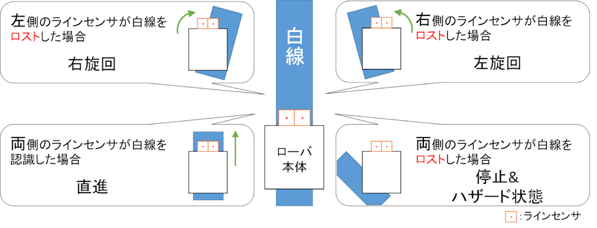
As shown in the diagram above, the tracing was done by moving forward until one of the sensors cannot detect the white line. As we used two sensors, it was easy to detect the curvature of the line based on which sensor left the white line first. This was then repeated in a loop until the rover reached an obstacle or the end of the mission. This solution proved to work well even for very sharp turns as the movement and checks were done at a very short interval.
The obstacle avoidance algorithm we implemented was as seen in the diagram below.
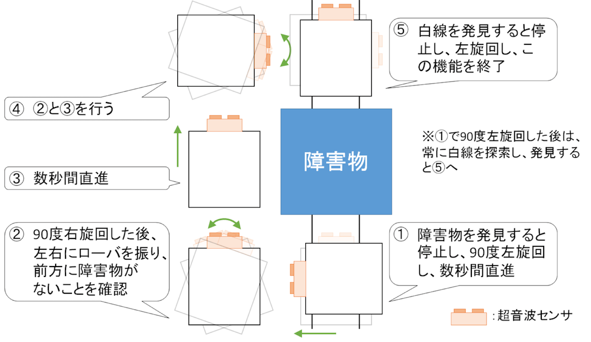
Using the sonic sensor, we detect whether there is an obstacle while tracing the line. If an obstacle is detected, a 90 degrees left turn is performed, and the rover advances forward for 30cm (the obstacle size was fixed) and makes a 90 degrees right turn. It then slightly turns left and right to see if any of the parts of the rover might hit the obstacle, and if the pass is clear, it advances for 60cm or until it reaches the line (in case the obstacle was positioned at the edge. It then turns right for 90 degrees, does the obstacle check again, and continues forward until it reaches the line again. Once the line is reached, it turns left and continues with the tracing of the line. If it cannot detect a line after a certain time, it notifies the ground station and waits for a command.
The end of the mission was detected using the gyro sensor. As soon as we detected a change in the angle (larger than a certain threshold), the rover would reverse back until it flattens out and send a notification that the mission is finished.
Mission 2: Crater Exploration
The second mission was all about exploration. In order to start the mission, the rover was instructed to enter the crater which was detected using the gyro sensor. While inside, the rover was meant to stay within the crater until all substances were detected, and then go out. The algorithm that was used to detect crater edges and obstacles is depicted below.
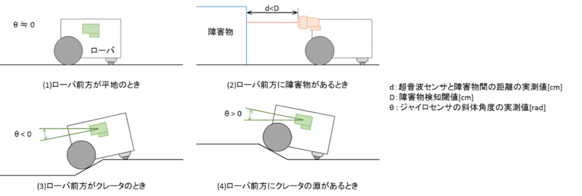
The obstacle detection was exactly the same with what was used from the first mission. The only difference was the avoidance algorithm. Instead of going around it, it would simply turn and start moving in that direction.
Using the gyro sensor, it is trivial to detect when the rover is going up an edge. In such case, it would reverse for a certain distance, turn at a random angle greater than 90 degrees in any direction, and continue straight.
As the turns after detecting an edge are random, it means the exploration of the crater was randomly executed. We considered making a more systematic exploration, but it proved to be much more complicated without any significant benefits.
Every time the color sensor detected a variation in the color, it would report the type of color detected to the ground station and it would continue moving forward. Further detection of the same substance was ignored.
Once all substances were detected, the rover was to move forward until it goes up an edge, stop there, and report to the ground station, which would conclude the second mission and the entire course.
Testing
One very big challenge that we had to deal with was the ability to test on the real course. As mentioned earlier, we only had one try at it at a predefined time for only 30 minutes. Unfortunately, we were not really ready at that time to test anything properly, which meant we have to find our own ways to do the testing.
In order to test on something resembling the real course, we had to improvise our own testing environment. After an hour of setup, some tape, and cardboard, we ended up with something like in the picture below.
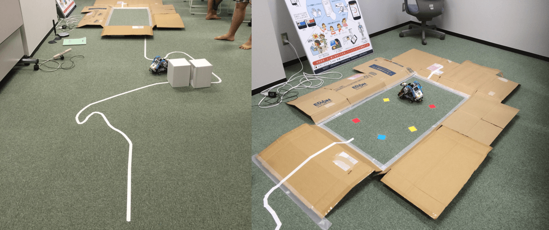
We wrote down a number of end-to-end test scenarios we wanted to try out and went on to test them one by one. Every time a problem occurred, we went and fixed it, and rerun the test. This allowed us to test the calibration step on different surfaces, tracing, obstacle avoidance, and crater exploration pretty successfully.
The Final Run
After countless hours of preparation, implementation, and testing, we flew to JAXA in Tsukuba, Japan, and started with the final run.
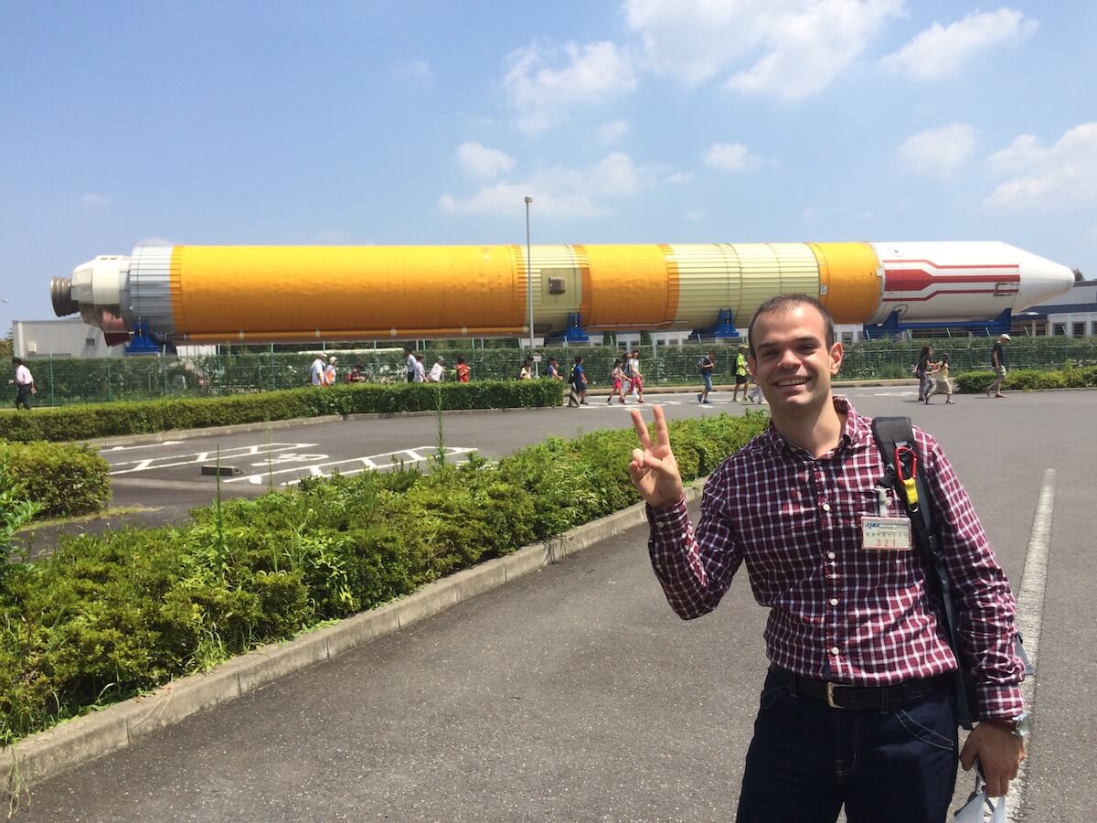
There were 8 teams, and we were second to last. Up until it was our turn, all teams failed to finish the first mission, which shook up our confidence a bit. When it was our turn, we carefully did our calibration and started the rover’s autonomous trip. Luckily for us, we managed to finish the first mission successfully.
The second mission started without a problem. We were hidden behind a panel and could not see what is happening with the rover. We got a visual (picture sent to an iPad) every minute, and the rover reported one substance. Watching the video later, the rover also avoided obstacles successfully. Just when we thought everything is going well, the rover started going around the crater edge without detecting it. This was due to one of the side wheels we installed for stability, and after about 20 seconds, the rover flipped on the Wi-Fi USB dongle, and it got disconnected! All our efforts ended here, with a lost connection and no way to recover.
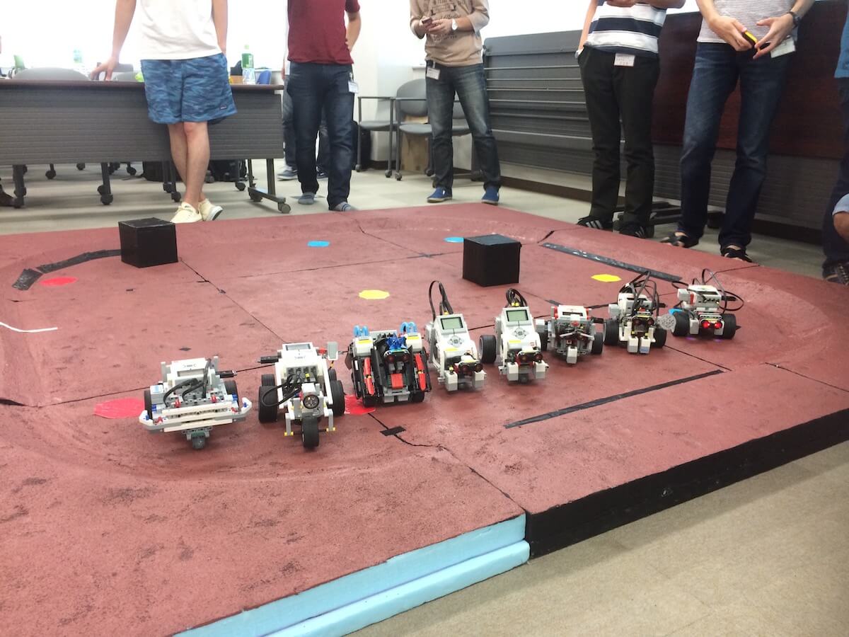
Despite all the preparations most teams have done, and all the efforts they put in, not a single team managed to finish both missions successfully.
Conclusion
A seemingly simple task ended in failure for every single team. It might have been the lack of time, the lack of experience, or maybe just the lack of motivation in doing a good job, but these are real-life problems as well. The same challenges and many more will show up in the real world, and we need to find ways to deal with each of them and still build a highly reliable system.
Aside from learning a lot on various topics, this experience was definitely an eye-opener about the much greater complexities a real Mars rover would imply, and how even the most unexpected events can be devastating for a project of such scale.
References
NAIST
IT Triadic
JAXA (Introductory materials for the course prepared by JAXA were used)
Raygun - 10 costly software errors in history
